Recently I discovered that my Time Pilot arcade PCB is broken. It works partly, its the graphics that is messed up. The cause is an eprom, where all of its legs on one side, just rusted off the socket. Some of these old PCBs are in rough shape. Not always treated well – especially after the video arcade games business was no longer profitable. So some stuff must have dripped on it and now (decades later) took his toll.
What has this to do with the topic of the post? Well a lot. I want to use my old C64 eprom programmer, to replace the broken eprom on this board. For that I need to move the eprom contents (which are available on the web, thanks MAME) from my PC to the C128D. A decade back I built a cable for the parallel port, to connect a 1541 drive. But PCs come these days rarely with a parallel port and it also quite an effort, to setup the drive on my desk and so on. The SD2IEC would make life a lot easier for this project. Ohh and I built one about 4 years ago for my C64 DTV.
The SD2IEC project has come a far way already and there are many different hardware layouts. The later versions need at least an ATMEGA 644. I had an ATMEGA32 sitting in a drawer and decided to go with less features, but without the need of ordering another micro controller. The SD2IEC I built is based on this layout:
 The drawing says ‘MMC2IEC’, well it is basically the same. The software is different, SD2IEC is a more up to date incarnation and at least the older one are using the same hardware. This is actually easy to build and doesn’t need lots of parts. You can bring the number of parts further down, by getting one of these Arduino SD card shields from eBay. It is literally then just one
 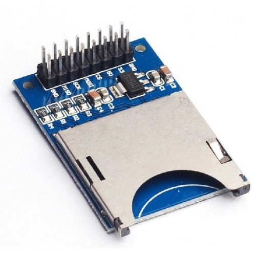 capacitor (even that is optional), plus two LEDs. Thats all. For the connection to the C128D we need a 6 pole DIN plug and either a connector for the user port or datasette port. The latter would provide the 5V power the circuit needs. The SD card reader needs to operate on 3.3v, otherwise it fries slowly the SD card. So thats what the other parts are for and the SD shield already comes with 3.3v power regulation.
I struggled to find a firmware, that can run on this layout with an ATMEGA 32. The last version that is compatible can be found here . Unfortunately it comes without binary, I attached the compiled version to this article. If you want to compile your own, you need to get e.g. WinAVR (free) and run make with passing a ‘CONFIG’ parameter:
make CONFIG=config-sw1
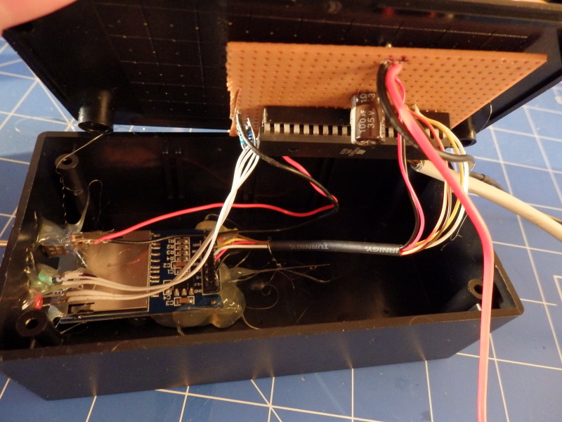
Btw, my attempts to compile it with my AVR toolchain under Linux failed – dont waste your time. This is how my board looked once finished.
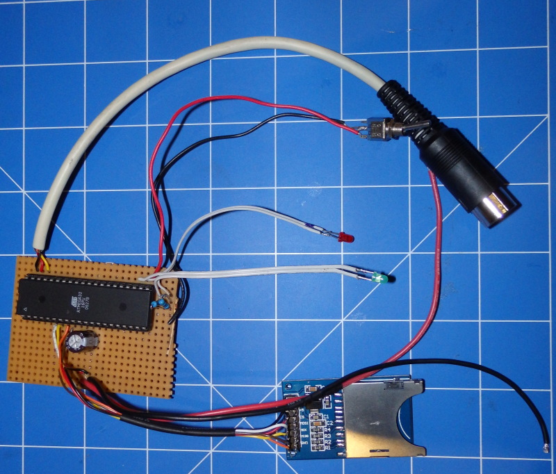
 The switch defines the device number. On my C128D with his built in drive, I need to have the SD2IEC running on #9, but on a C64 I would prefer #8. The next step will be flashing the firmware and finalizing the wiring. For flashing I prefer to use avrdude, this will flash the hex file and also set the correct fuses:
avrdude -p m32 -c usbasp -P USB -U lfuse:w:0x94:m -U hfuse:w:0xd9:m -U flash:w:sd2iec.hex
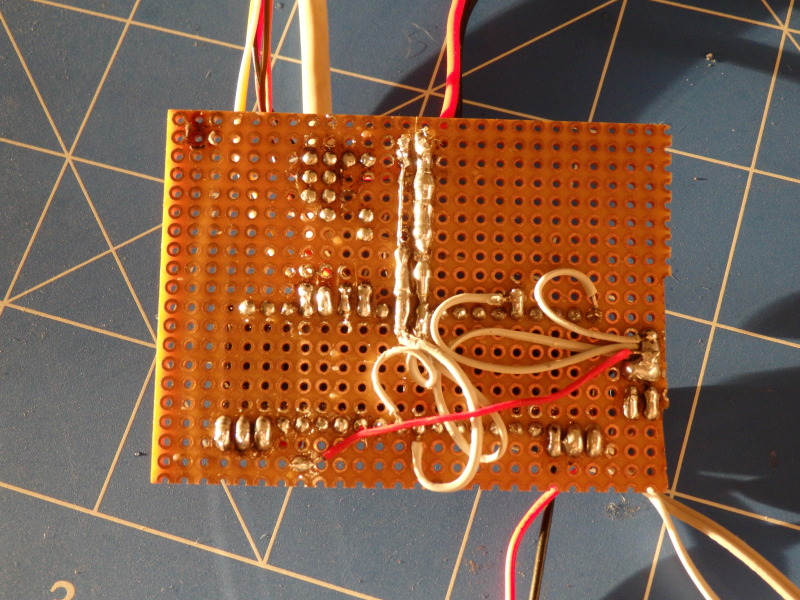
I flashed the ATMEGA in a breadboard, for that purpose I just built a small connector. That way I can use my breadboard always as a ‘flashing station’.
The small adapter connetcts the 6 relevant pins for programming directly to plug that fits into the 10 PIN connector of the USBASP. Without any issues, I was able to flash the ATMEGA that way. I did not add an ISP connecto to the circuit board. If I need to reflash the ATMEGA, I just get it out of the socket and flash it on the breadboard. That makes the SD2IEC board a little more compact and I have a little less to solder.
The SD2IEC should just work with the 3 wires for the serial connection plus a 4th for Ground. Even is the SD card adapter is not connected correctly, you should be able to run the little test program below. When you turn it on, the red LED should flash for a quarter second – that is the first indicator that it does what it should.
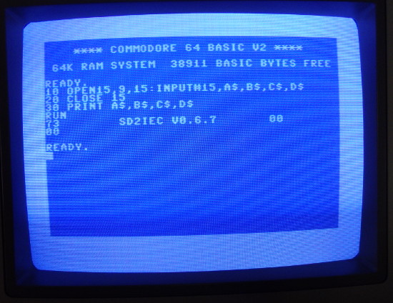
When you see this message, all looks good already. To ‘mount’ a D64 image file, you need to use a command line like this:
open 1,9,15,”CD:summergames.d64″:close 1
 You would use ‘8’ instead of ‘9’. My C128D got already an internal drive and that’s why its running for me on ‘9’. Above example also needs to be adjusted to the correct drive number you use (test program and mounting of D64). The command structure of Sd2IEC is totally different compared to MMC2IEC.
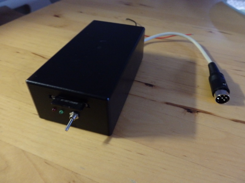
Once I was sure all is running fine, I decided to put the whole thing into a case I got for $5 from an electronic store close to my place.
Not my prettiest thing I ever built, but it does what it should.
Here is an overview of the other commands:
SD2IEC can deal with folders, so with open1,8,15,”CD:/MYFOLDER” you would change into a sub-folder on the SD card. To navigate back you use “CD_” where _ represents the left arrow on your C64/C128 Keyboard. You can also use “MD” to create, or “RD” to delete directories. PRG files can be loaded directly. I also attached the original README to this article for reference. There are a lot more commands! Btw, the way SD2IEC deals with D64 images, makes it compatible with tools like D64it. You can write from an image back to a physical disk without issues. That’s something that did not work with MMC2IEC.
Useful Links:
Hi,
Can you please help me with connecting layout to SD module?
I have same SD module as you, but different layout (Atmega 644p by LarsP 2009). What should I do with the SD CARD DETECT and SD WRITE PROTECT connections – I have it on layout, but I don’t see it on SD card module?
What voltage is better to connect to module? I have both 3.3 and 5V on layout?
Thanks
grebuz
Hi Grebuz,
as far as I remember I put both of them on ground. I think its mentioned in one of the links as well. I am running the module on 5V.
Let me know how you go.
Holger
You have written “The small adapter connetcts the 6 relevant pins for programming directly to plug that fits into the 10 PIN connector of the USBASP.” which implies that we know how to do this – sadly this is not the case and means your step by step instructions cannot be followed.
Hi Mike,
This step is just about programming an AVR in general. All information around that on the web is suitable for this tutorial, if you have never flashed an AVR before. I just built a ‘connector’ to be able to do it the lazy way, if I have to flash it again. You can find some additional information for example here: http://www.ladyada.net/learn/avr/programming.html
I would like to explain how to connect the sd pins (I think it is 9) to the ATmega32, if you can do a drawing.