So its time for the next part of the Quadcopter project. After being done with the rather mechnical stuff, its time to give the ESCs some attention. We got 4 of them, each motor will have its own and they will be mounted on each of the arms. The ESCs will source the power from the “Power Distribution Board” I purchased, which is a lot nicer than soldering all black and red wires together and add a plug. The board comes with 3.5mm female connectors onboard, so the ESCs can be removed easily. I am using the same connector type on the motors. So if I want to use the ESCs on another quad, I can theoretically shift it easily to the other aircraft. But that will only work, if the arm length is the same. The wires of the ESC need to be changed to optimal size, its difficult to stuff extra wire somewhere and it doesn’t look nice. Also the ESC itself should be placed on the arm and not half way in the frame. So lets get our ESCs right.
ESC Preparation
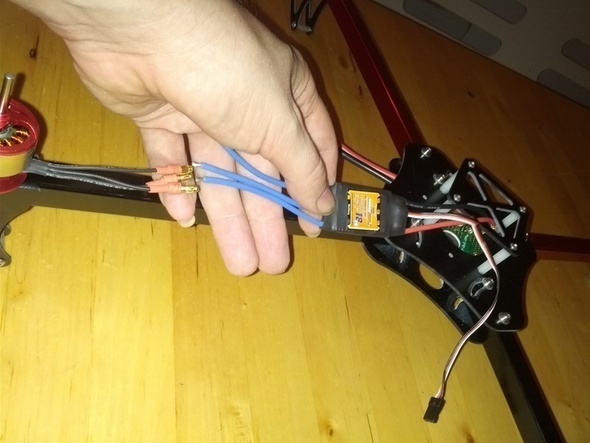
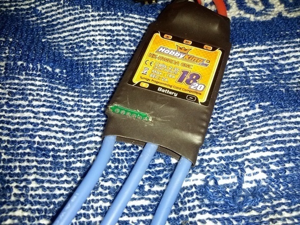
As you can see, the size of wire is not ideal. I need to reduce the length of the blue wires, to have the ESC somewhere on the arm. Also they can’t be too short, otherwise I will be out of reach of the plugs on the power distribution board.
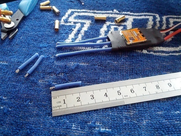
To cut a little bit more than 2cm seemed to be a good fit. After adding the connectors, it will gain again a few mm of length.
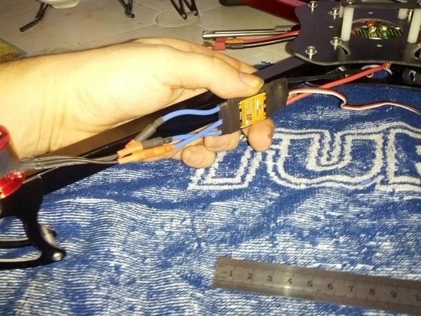
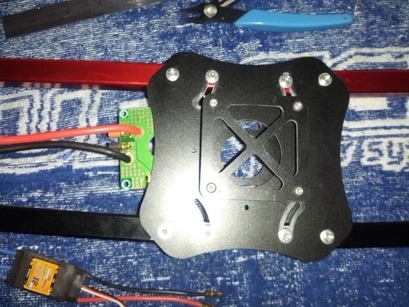
The final result looks ok. I temporarily placed the power distribution board into place, to see how it fits. Time to prepare the remaining ESCs, including the plugs and shrinking tube.
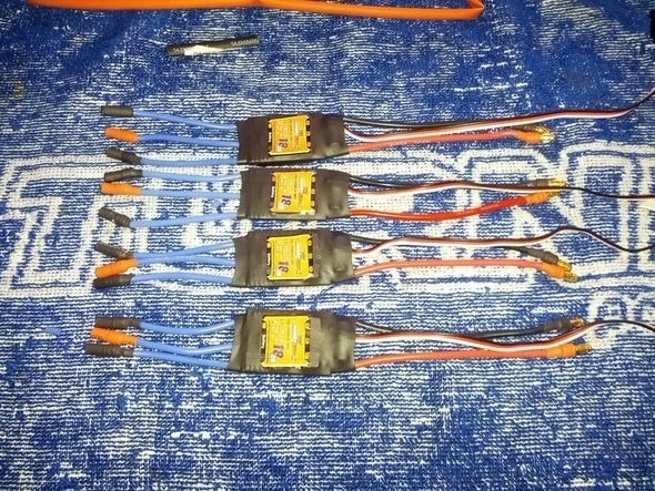
So all 4 are preparted. I like to have the middle motor connector in a different color. It makes it easier to recongnize the way it is connected to the ESC. Switching the order of two of the plugs, will change the running direction of the motor. We will have two counter and two clockwise rotating motors later. Its also a good time to fix with some double sided table the power distribtution board.
You can only move it in and out, when folding the arms. Otherwise they are in the way. Might also be a good idea to already install when assembling the frame.
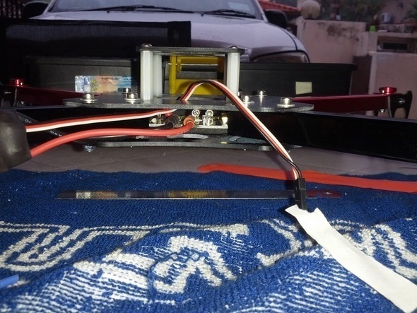
Hard to remove the paper off the sticky tape, space is really limited here and I am a bit worried when you compare the amount of available space with my other quad.
So its perfectly in place and the power wires from the ESC fit nicely.
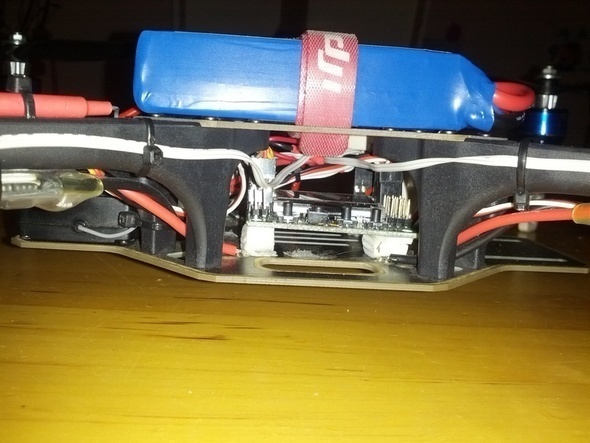
Same view from my F450 quad. Here is plenty of space and the power distribution is part of the frame. But I am not complaining, this frame was $80 and the X550 just $20…
For the ESCs I am planning a reflash. They are equipped with Atmel Microcontrollers and we need six straight connection to the flashing related pins. Luckily these HK-18A ESCs are having six pads on the corner of the circuit board. These pads are wired to the pins we need. Convenient!
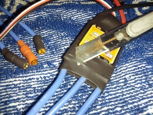
What I am doing is carefully cut the shrinking tube in the right spot open, to get access to the pads. For the future it will be always easy then to reflash them.
Here are the six pads now visible and easy access is granted.
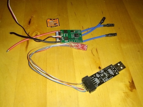
For the flashing we need an AVR Programmer and to ease the process, I have built a little tool which will connect to the programming pads, without any soldering.
The AVR USB Programmer and the ESC without any shrinking tube for illustration.
So based on that pic everybody will get the idea. It was not a fun job to build this little tool from wire and hot glue. But it pays out when you plan to flash many ESCs of the same type. Btw, not all ESCs are having these pads lined up so nicely… I flashed already about 10 of this particular type like this.
In the next part I will talk about the ESC flashing process. This part is not mandatory, the Quadcopter would also fly with the original firmware on them. But the performance of the quad is so much better, that the effort is it worth.
